
This command can be used to add slant edges to the sharp corners, these slant edges are also called chamfers. This command can be used to add rounded corners to the sharp edges of the geometry, these round corners are also called fillets. This command can be used to explode objects like Polyline to simple lines, an array or a block to a simple geometry etc. Using this command you can open text style window which controls properties of the default AutoCAD text style. This command can be used to insert an existing block or a drawing as a block in AutoCAD. This command is used for creating a block, the properties of the block can be defined using the block definition window. This command is used to change the scale of an object. Using this command you can open options window which contains most of the settings of AutoCAD. This command is used for trimming a geometry. Using this command you can make Rectangular, polar or Path array. This command is used to copy object(s) in AutoCAD. This command can be used to make a region geometry in AutoCAD. ELLIPSEĪs the name suggests, this command can be used to make an ellipse with the major and minor axis. ARCĪs the name suggests, this command can be used to make an arc in AutoCAD. This command can be used to make a polygon with minimum of 3 sides and a maximum of 1024 sides.

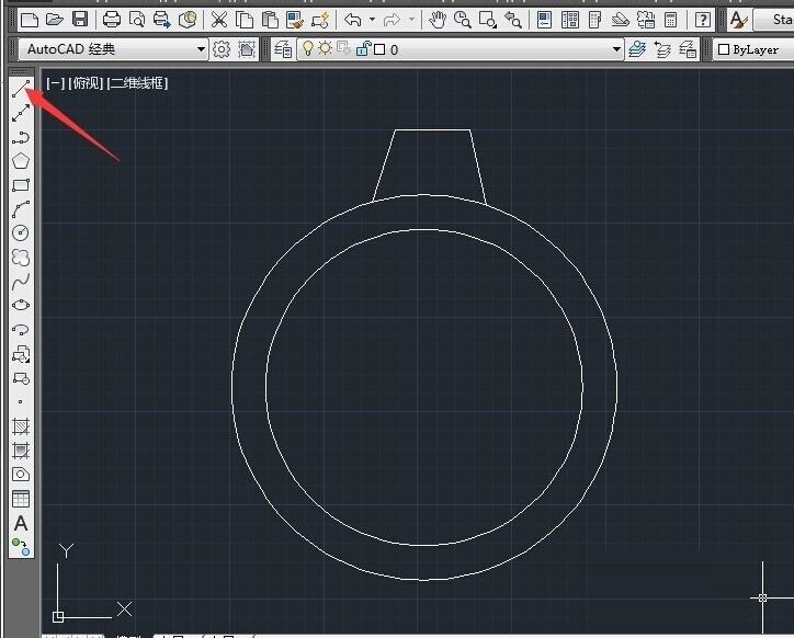
This command will make a rectangle in AutoCAD. This command can be used to make a Polyline in your drawing. It is the command used for making a circle in AutoCAD. It can be used for making simple lines in the drawing.

These are some of the Draw and Modify commands which make the very basics of AutoCAD and if you are just starting to learn AutoCAD then you should know all of these basic commands. The resulting drawing sheet can be exported to a separate DWG file ( EXPORTLAYOUT).This is the list of some of the most basic AutoCAD commands which every AutoCAD user should know. All created view representaions can be associatively dimensioned. When the model is updated, the user is prompted to update the drawing views. These documentation commands create projections in the selected directions - orthographic or isometric, you can specify the display style (shaded, hidden lines, tangencial lines.). so you can create the drawing views also from these sources of 3D CAD models (formats). But the 3D model inside the DWG drawing can be also imported from SolidWorks, Rhino, CATIA, Pro/ENGINEER, ACIS, Parasolid, IGES, STEP, JT etc.

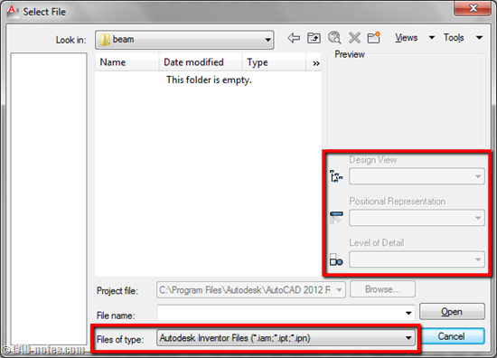
If there is no 3D object in the given DWG file, the command offers view generation from external Inventor 3D models (. If the model space of the current drawing contains a 3D object, the 2D views are generated from this 3D model. The VIEWBASE command in AutoCAD 2012 (2013,2014.) can conveniently generate 2D views (projections) of any 3D solid. AutoCAD 2012: Generate 2D drawing views from 3D models.


 0 kommentar(er)
